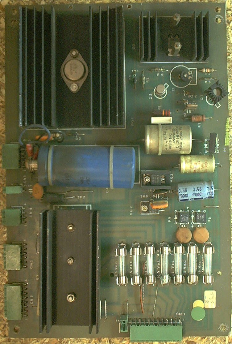
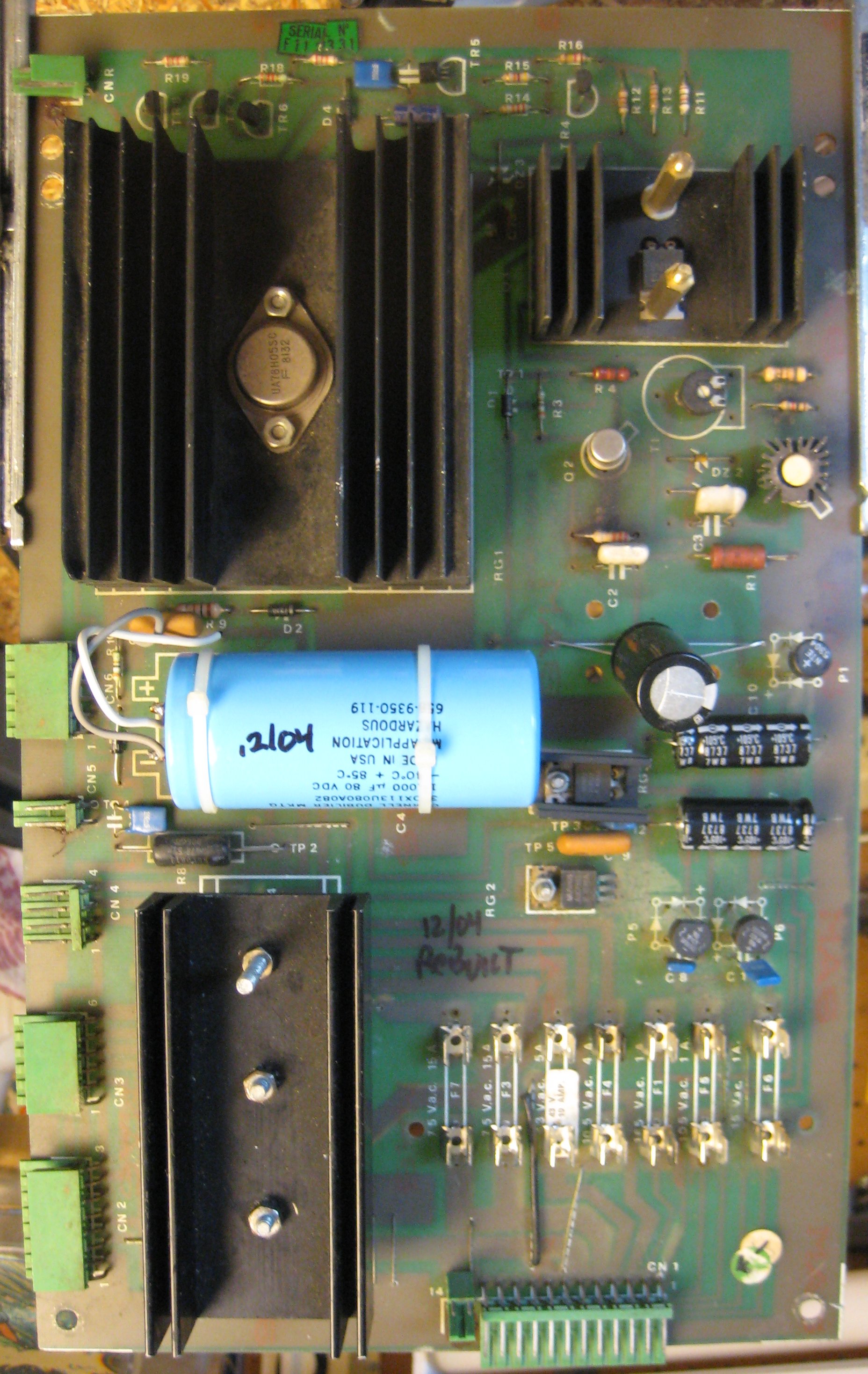
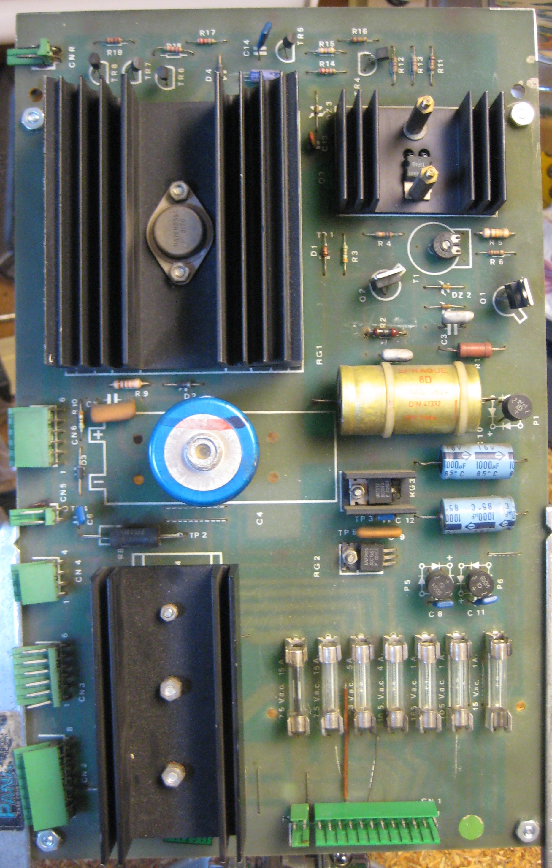
The power supply board takes the input voltage from the transformer in the main cabinet, and generates the +5, +12, +39, +170 and -5 voltages needed for the logic, lamps, solenoids, and display circuits.
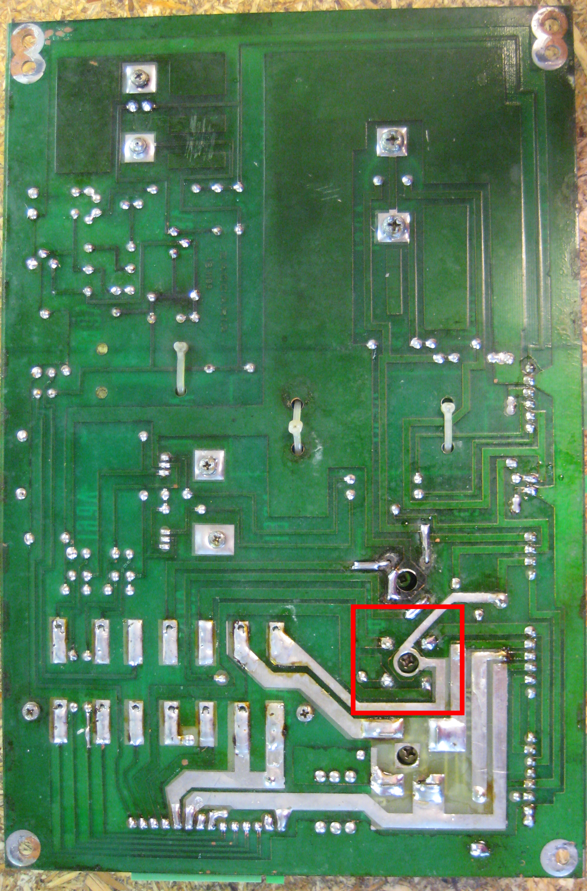
The input connector at the bottom right corner (CN1) of this board can overheat with time, especially on the pins that feed the General Illuminiation (GI) lamps, scorching the housing and building up resistance in the connector pins. On later games, they doubled up the GI input pins, spreading the load over two sets of two pins to reduce this problem. Check here for any signs of overheating and replace the connector and header as necessary.
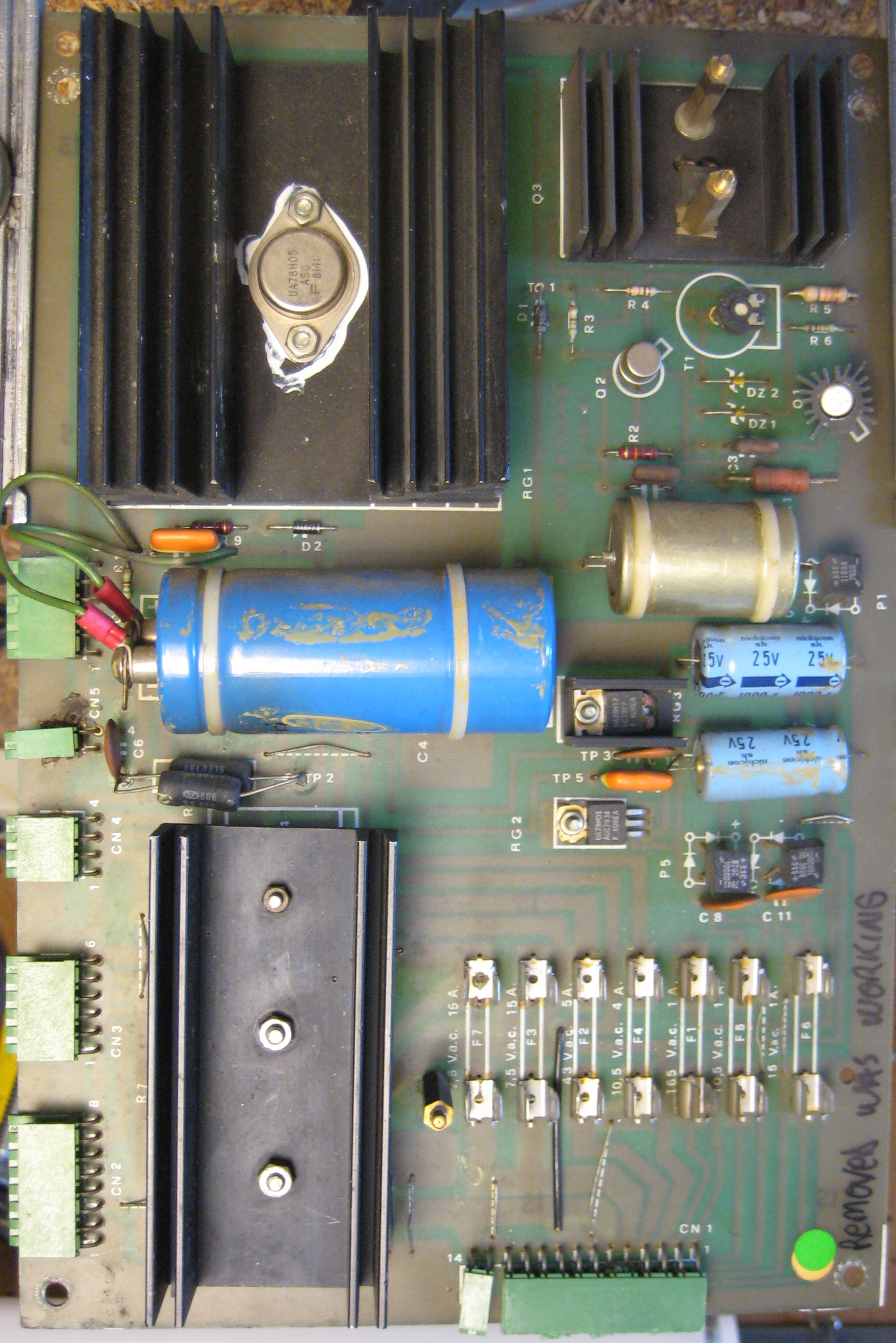
The fuse clips used are cheap and tend to corrode and weaken over time. They are also a non-US-standard size. Replace all of the fuse clips with high-quality ones (like the ones Mouser sells as part number 534-3513). To do this, the board will have to be modified by drilling holes to mount the clips properly. The solder pads for the fuse clips are large enough to allow 2 holes to be drilled to allow a normal fuse clip to be soldered in place. Enlarge one hole on each side, and add one new hole to fit the new fuse clip in place.
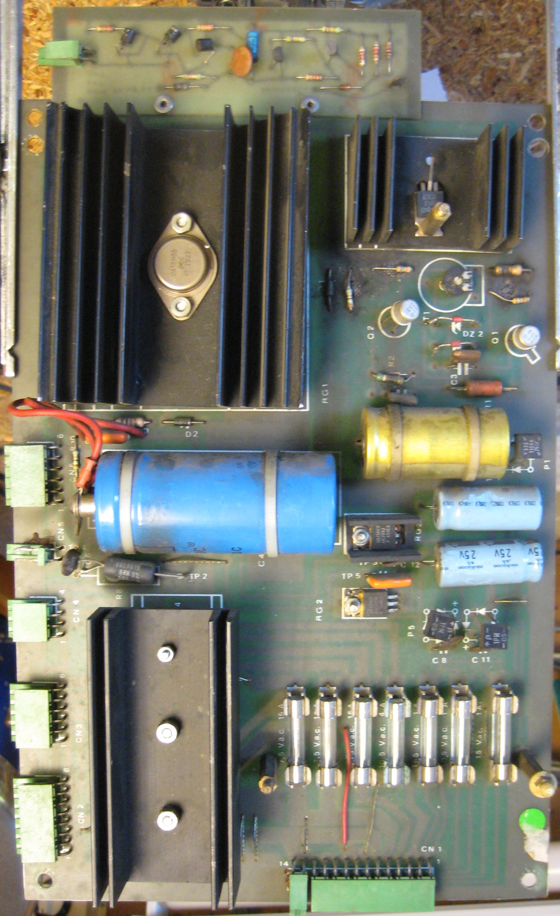
There are three bridge rectifiers mounted under the large heat sink in the middle of the power supply board. If one of them fails, you should replace all three of them while you already have the board out and are working on it. They are lug-type bridges and require a soldering iron that can deliver enough heat to work a large joint. Don't try this with a 15W Radio Shack soldering pencil!
The schematic / parts list calls for these bridge rectifiers:
| Bridge Rectifier | Part Number | Rating |
|---|---|---|
| P2 | KBPC 1002 | 200V 10A |
| P3 | KBPC 10005 | 100V 10A |
| P4 | KBPC 8005 | 50V 8A |
You can substitute a higher rating for any of these. These:
| Bridge Rectifier | Mouser Part Number | Rating |
|---|---|---|
| P5 | 583-MP254 | 400V 25A |
Before trying to troubleshoot a game in an unknown state, verify that the transformer is configured for the correct line voltage and has the correct fuse installed for your line voltage, then verify that the power supply is getting the correct input voltages and producing the correct output voltages.
Disconnect CN1 from the power supply board and test the transformer first. The correct way to test a transformer with a meter is to read voltages between pairs of pins in the connector. Do not attempt to read a voltage compared to the chassis ground, you will get approximately half the voltage reading that you would expect to see. Put your DMM on the appropriate VAC range before testing each pair of pins in this connector.
| Pin 1 | Wire Colour | Pin 2 | Wire Colour | Voltage |
|---|---|---|---|---|
| 1 | Red | 2 | Red | 165VAC |
| 3 | Blue | 4 | Blue | 43VAC |
| 5 | White | 6 | Green | 7.5VAC |
| 7 | Yellow | 8 | Yellow | 10.5VAC |
| 9 | Brown | 10 | Brown | 10.5VAC |
| 11 | Black | 12 | Black | 15VAC |
| 13 | White | 14 | Green | 7.5VAC |
(Pins 13 / 14 are not present on early games using the original 1B1109 power supply. These are the doubled-up GI lamp connection to help prevent scorching of the connector at pins 5 / 6.)
After verifying the input voltages from the transformer, turn the power to the game off and reconnect CN1 to the Power Supply board. Disconnect the connectors from the Power Supply that go to the other boards in the backbox. Turn the power on, and verify that the power supply output voltages are correct at the test points, or at the connector pin:
| Test Point | Location | Voltage | Connector / Pin |
|---|---|---|---|
| TP1 | Top of Diode D1 | 170VDC | CN6 / 6 |
| TP2 | Right leg of Resistor R8 | 5.3VDC | CN6 / 4 |
| TP3 | Left leg of Capacitor C12 | 12VDC | CN6 / 3 |
| TP4 | Top of Capacitor C6 | 5.6VDC | CN5 / 2 |
| TP5 | Left leg of Capacitor C9 | -5VDC | CN6 / 1 |
| TP6 | Top of Resistor R7 | 39VDC | CN3 / 6 |
Put the black lead of your DMM on a convenient Ground connection, like the base of resistor R7, and use the other lead to probe these test points. On some boards, there are nice little wire loops soldered to the test points. On others, there are none. Some early revisions of this board may not even have test points, so you may have to check at the component or connector pins.
If the output voltages appear to be correct, turn the power off, and reconnect the wiring harness between the Power Supply and the CPU. Leave the other connectors from the Power Supply that go to the Driver board and cabinet/playfield disconnected. Disconnect the ribbon cable from the CPU board that goes to the Driver board. Disconnect the connectors from the CPU that go to the switch matrix. This leaves just the Power Supply and the CPU connected. Install one display on the ribbon cable that goes to the backbox door, and remove the other displays (and Sound board, if present). Procede to testing the CPU.
There appear to be at least six revisions to this board, possibly as many as eight. I have or have seen examples of 1B11109, 1B11109/0, 1B11109/3, 1B11109/3 + 1B1134, 1B11109/4, and 1B11109/5. Based on their usual numbering scheme, there should be 1B1109/1 and 1B1109/2 but I have not yet seen examples of those.
Used on the earliest of the solid state games (Winter Sports, House of Diamonds, Future World), this is the basic board design that the others are all based on. CN1 on this board is a 12-pin AMP MODU-1 connector. Since only two pins are available for the General Illumination, this connector tends to overheat and scorch.
Used on Shooting the Rapids and Hot Wheels, the first revision to the board design which corrects the overloaded GI connector problem by adding a second 2-pin MODU-1 (CN1A) and a second fuse (F7) to double the current capacity for the GI circuit. The board is still labled 1B1109, but the schematics show the change.
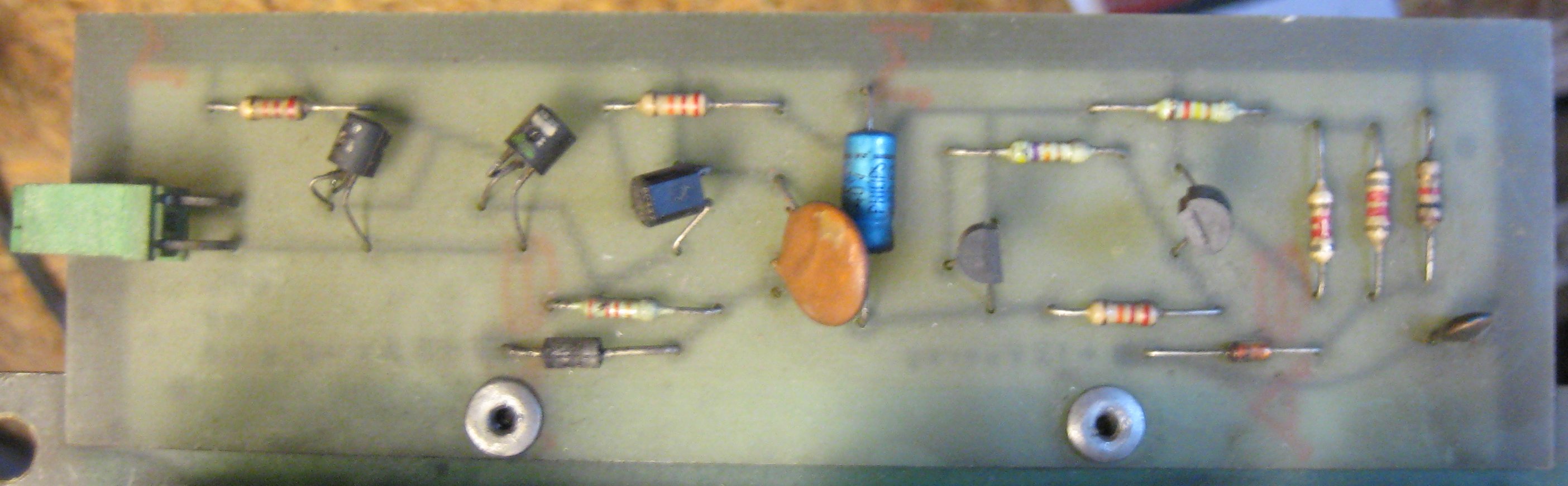
A customer repair board from a Hot Wheels, this board is still labled 1B1109, but it has the extra 2-pin connector for the GI circuit from the 1B1109/0 revision. It also has a wire lead bridge rectifier at P2, with no provision for the usual lug lead bridge to be installed.
Unknown. So far, no printed reference or schematics for these revisions have been found, and I haven't heard from anybody with a game with a board in it with one of these designations.
Unknown. So far, no printed reference or schematics for these revisions have been found, and I haven't heard from anybody with a game with a board in it with one of these designations.
This appears to only have been used on Fire Mountain. Other than the part number changing, it appears to be identical to the 1B11109/0.
Probably used early in the Star God run. May also have been used in some Space Shuttles. This modification to the 1B11109/3 board adds the 1B1134 "power down" circuit by having it pop-riveted to the top of the board and tied in to the +12V and +5V at RG1 with wires soldered to the back of the board. I assume that they were using up a supply of 1B11109/3 boards before starting to use the 1B11109/4.
Used on Star God, Space Shuttle, Earth Wind Fire, and Locomotion. The 1B1109/4 adds a section labled "Power Down Circuit" to the top of the board, making it about 1" (2.5cm) taller. This circuit is there to ensure that the required voltage levels are present and hopefully stable before the processor is allowed to boot. A new 2-pin connector, CNR, is added to the board, though only one pin of it is used to connect the output of this circuit to the CPU board at CN9 pin 8. On initial power up, the processor's reset line is pulled Low by TR8, preventing it from booting. The +12V circuit on the power supply is monitored, via Zener Diode DZ3. When the +12V is present, TR8 is switched off, and the reset circuit on the CPU board is able to pulse the reset line High to boot the processor. Fuse F2 has a sticker calling for a 10A fuse; on previous renditions, the board silkscreen says 5A fuse here.
This was probably used late in the Locomotion run. I have no reference material for it, and it seems to be the same board as the 1B11109/4.
These two items would not ordinarily be found together, but it turns out that the GI lamp circuit is critical to the operation of these games. Without it, the game cannot boot. The reason is that the bridge rectifier P3 on the power supply board takes its AC input from the GI lamp circuit, and is labled as being a +5.3VDC (VRM) power supply output. Tracing this through the schematics, the only place it is used is to feed the RESET circuit on the CPU board. So, without a working GI lamp circuit, the CPU cannot start and the game will not boot. This makes the scorched connector problem on the 1B1109 board even more problematic, since it would affect the GI circuit input on the board, leading to a non-working game when the connector fails.
On the 1B1109 (Winter Sports) schematic, the VRM power supply output is labled as +7.5VDC. It should be +5.3VDC. This was corrected on the 1B1109/0 schematics (Hot Wheels).
David Gersic
Copyright © 2001. All rights reserved.
This document may be freely distributed so long as the content is not modified.