"I turned the game on, there was a 'pop' noise, and fuse F2 on the power supply board blew immediately. What do I do...?"
The problem here is usually a simple one: one of the TIP102 "drive" transistors on the driver board has failed. These control the various solenoid driven devices on the playfield, running at 39V. Finding the culprit, with a minimum of fuses blown, can be frustrating, since replacing the fuse and turning on the game results in a quick bang, flash, and another blown fuse.
The way the solenoids work is that the 39V power leaves the power supply via CN2, is routed via the wiring harness to all of the solenoids on the playfield and in the backbox, and then returns via the driver board at CN17. All solenoids have power, all of the time. So, technically, the TIP102 transistors at the lower right corner of the driver board are actually "sink" not "drive" transistors, since they take the voltage that is already present and "sink" (ie: "switch") it to ground to complete the circuit.
Since the voltage is always there, if the TIP102 fails, it will fail in one of two ways. If it fails "open", it simply stops working and the device it controls will no longer fire when it should. This is easy to diagnose. But, if it fails "closed" or "shorted", then the situation becomes more difficult. When this happens, the solenoid coil is always on. This results in it drawing too much current, which blows fuse F2 to protect the power supply circuit board and the wiring harness from more catestrophic failures.
A word here about over-fusing or installing a fuse rated for an amperage that is higher than called for. Fuse F2 is a 5A fuse. This means that when the circuit it protects draws more than 5 amperes, the fuse blows. This much current going through the connectors, wiring, and circuit board would cause parts to burn up or the wiring harness insulation to melt and possibly catch fire, this fuse value is important. Installing a 10A, 20A, or some other higher rated fuse here, or bypassing the fuse with a nail, bolt, length of wire, .22 shell casing, etc. is only going to result in more and more catestrophic failures down the line. Do NOT over-fuse anything. If the 5A fuse is blowing, there is a reason for it. It is protecting you from other failures that will cost you much more than a 25 cent fuse will. Fix the problem, then replace the fuse with a new one of the correct rating.
Troubleshooting begins with getting the game in to a state where you can actually work on it, without losing more parts than necessary. You will need to be able to turn the game on. So, remove the wiring harness connectors at the bottom right edge of the driver board (CN17). There are two 12-pin .156" headers here, though not all games use all pins of this header, and most games use three or more wiring harness connectors here. Lable your connectors as you remove them, so that you can reinstall them later. The game originally had paper lables glued to the connectors, but these are usually long gone by now.
Now, with the game off, replace fuse F2 with a new 5A fuse.
Last, remove connector CN3 from the power supply board.
It should now be safe to turn the game on. There will be no controlled lamps flashing, and no solenoids will work, but the game should power up without blowing fuse F2.
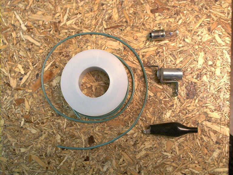
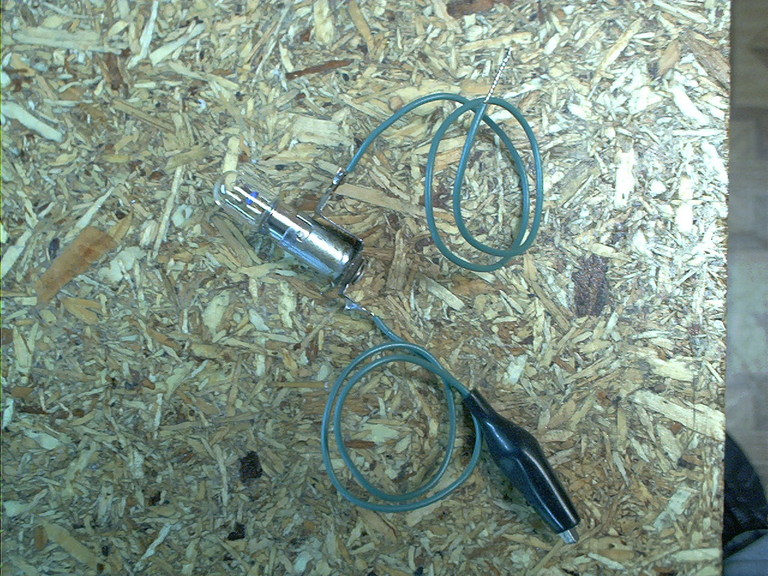
Build the following contraption:
|
 |
 |
With the game off, connect one of the aligator clip leads to CN3 pin 4 on the power supply board. Then turn the game on. Be careful not to let the other aligator clip touch anything just yet. Again, the game should boot and go in to attract mode, just with no flashing lights or working solenoids.
Use the Advance switch on the coin door to put the game in to its self test mode. The Displays test will start. Leave this running.
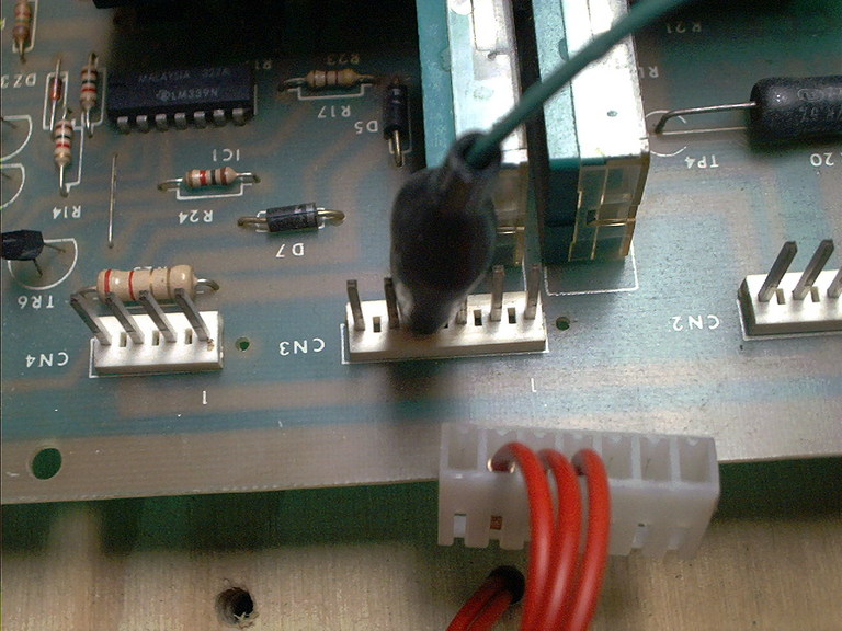
Now, using the other aligator clip, touch each pin of the 24-pin header on the Driver board. I usually work right to left, since that's the order that the pins are numbered in, but you can do it in either direction. Note any (all) pins that cause the lamp to light. None should, but one or more will, since we are hunting for a shorted transistor here.
 |
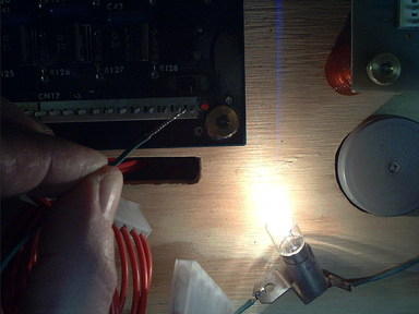 |
| Transistor OK | Transistor Locked On |
When you have identified which pins cause the lamp to light, use this table:
|
|
to find the transistor associated with that pin. This (or these, if you found more than one) is the first part of the problem and will need to be replaced. Either replace it (requires moderate soldering skills) or have it replaced by somebody comfortable with circuit board repair work. Regardless of the part number that may be printed on the transistor, use a standard TIP102 to replace it with. Watch out for previous repair work here, especially if this game is new to you and came with this problem. Complete this repair before continuing.
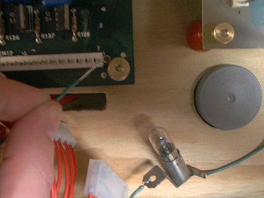
Reinstall the driver board and re-test with the lamp and socket in the game's self test mode. Now, no pins should be lighting the lamp.
Use the Advance button on the coin door to put the game in to the Solenoids test mode (#4). Use the lamp and socket to verify that each pin flashes the lamp when it's solenoid test number (see above chart) comes up.
Once the board passes the test both ways, then it should be safe to reinstall it in the game. For any transistors that were shorted, or physically damaged looking, check the diode(s) on the coil associated with that transistor to ensure that they have not failed. A shorted coil diode will destroy the transistor the first time the game tries to fire that coil. An open coil diode may allow the coil to fire a couple of times, but will also destroy the transistor.
David Gersic info@zaccaria-pinball.com
Copyright © 2005. All rights reserved.
This document may be freely distributed so long as the content is not modified.