

Required:
Suggested:
The switch matrix is an 8 x 8 array, allowing for 64 switches to be used in the game with a minimum of components and wiring. See the upper right quadrant of the cpu board schematics. The switch matrix is composed of IC33 which is written to by the cpu to strobe the matrix. The signals go from there, through IC41, to TR3 (Row 0) and IC38 (Row 1...7). Out from there, to the playfield itself, then back in on the columns (Col 0...7) via IC25 and IC15 where the cpu can read the results.
From the main page for each of the generations of games, there is a Games and Documentation link. Find the game being tested, and print out a copy of the switch matrix chart. This will help keep track of which switches have been tested. During the test, you will be moving down one row at a time, and across each row through all of the columns.
The assistant is suggested as you will need some way to see the Ball/Credit display, while the backbox door is open and you are working with the CPU board. A mirror, or some temporary location of the Ball/Credit display to somewhere visible, may also help.
|
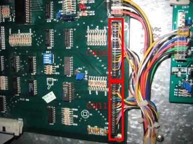
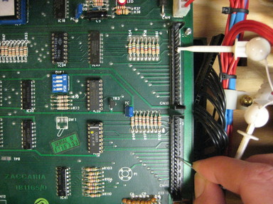
To begin, remove CN10 and CN11 from the CPU board. |
|
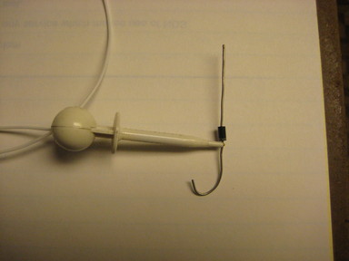
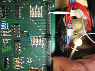
Clip one end of the wire lead to the diode on the banded side. |
|
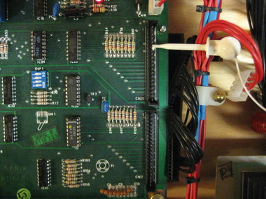
Clip the other end of the wire to CN10 pin 6. |
|
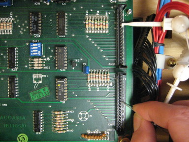
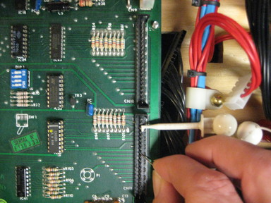
Use the unbanded side of the diode as a probe, and touch it to CN11 pin 10. This should act as if the Test Advance switch on the coin door had been pressed, putting the game in to the Displays Test. Touch CN11 pin 10 again to enter the Switch Matrix Test. |
|
Continue to use the unbanded side of the diode as a probe. Touch CN11 pin 11. This should display '01' on the Ball/Credit display. It may also act as Test Return, putting the game back in Displays Test. If so, touch pin 10 again to return to the Switch Matrix Test. |
|
Touch CN11 pin 12. This should display '02'. If at any time the wrong number is displayed, you have found a problem with the CPU board which will need to be repaired. |
|
Touch CN11 pin 13. This should display '03'. Continue with pin 14 ('04'), pin 15 ('05), pin 16 ('06'), and pin 17 ('07'). That completes testing of the first row of switches. |
|
Move the clip lead from CN10 pin 6 to CN11 pin 2. This begins the test of the second row. Touch the probe (diode) to CN11 pin 10 ('08') through pin 17 ('15'), one at a time. That tests the second row of switches. |
|
Move the clip lead from CN11 pin 2 to CN11 pin 3. This begins the test of the third row. Touch the probe (diode) to CN11 pin 10 ('16') through pin 17 ('23'), one at a time. That tests the third row of switches. Each row uses the same 8 pins of CN11. |
|
To test the remaining rows, move the clip lead to CN11 pin 4, 5, 6, 7 and 9. For each row, probe CN11 pins 10 through 17 with the diode. |
Testing the switch matrix on the CPU only takes a few minutes. If, at any point, an unexpected number shows up in the Ball/Credit display, there is a problem with the board that will require repairs. If all 64 switches test correctly, then the board is ok.
David Gersic info@zaccaria-pinball.com
Copyright © 2007. All rights reserved.
This document may be freely distributed so long as the content is not modified.