As the games and technology evolved through the 1980s, the 2nd generation games used different sound boards with varying sound and speech capabilities. There are four sound boards, and one daughterboard.
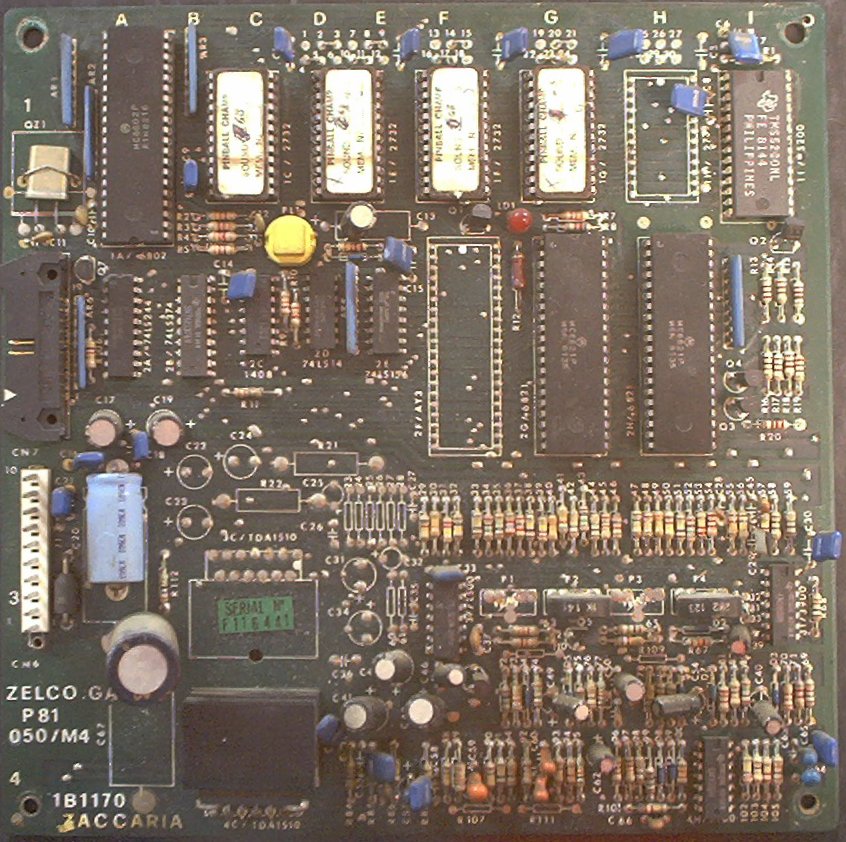
Used on Pinball Champ, Soccer Kings, and Pinball Champ '82, this board features both sound and speech capabilities. A 6802 CPU on the board does the work, and will run independantly of the game's CPU board. Electronic sound effects are generated via a GI AY-3-8910 and/or a 1408 DAC, and sampled speech clips are recorded in ROMs on the board played via a TMS5200 speech chip. There are adjustment pots for each circuit to adjust their relative volume (P2 is for the Sounds, P4 is for the Speech), and a final mix and amplification stage that feeds the sound to the single speaker mounted in the bottom of the cabinet. There is a volume pot mounted near the coin door to adjust the final volume. There is a self-test button on the sound board that will confirm that the board is working, though the game's built in diagnostics actually run through all of the sound and speech items in the ROMs. Not all games used the AY-3-8910; if not used, it was not installed on the board. Pinball Champ does not use the 8910, but Soccer Kings does.
Pressing the self test button on this board causes the board to perform several self checks which are confirmed by the LED flashing, then play a couple of sounds and at least one speech clip from the ROMs. This can be done with the Sound Board disconnected from the CPU to confirm that the board is working independantly.
The LED flashes and their meanings:
| Flash | Test |
|---|---|
| 1 | CPU RAM tested OK |
| 2 | PIA 1 (IC15) - Sounds tested OK |
| 3 | PIA 2 (IC14) - Speech tested OK |
| 4 | Sound generator tested OK |
| 5 | Speech synthesizer tested OK |
The silkscreen on the board indicates 2732 type ROMs are used. This is wrong. The board uses either 2532, or 2716 ROMs, depending on the game.
Jumpers: For 4 x 2532 ROMs, jumpers 2/3, 4/5, 8/9, 10/11, 14/15, 16/17, 20/21, and 22/23 should be installed. For 3 x 2532 and 1 x 2716 (Pinball Champ GB), jumpers 2/3, 4/5, 8/9, 10/11, 14/15, 16/17, 20/21, and 23/24 should be installed. Note the change from 22/23 to 23/24.
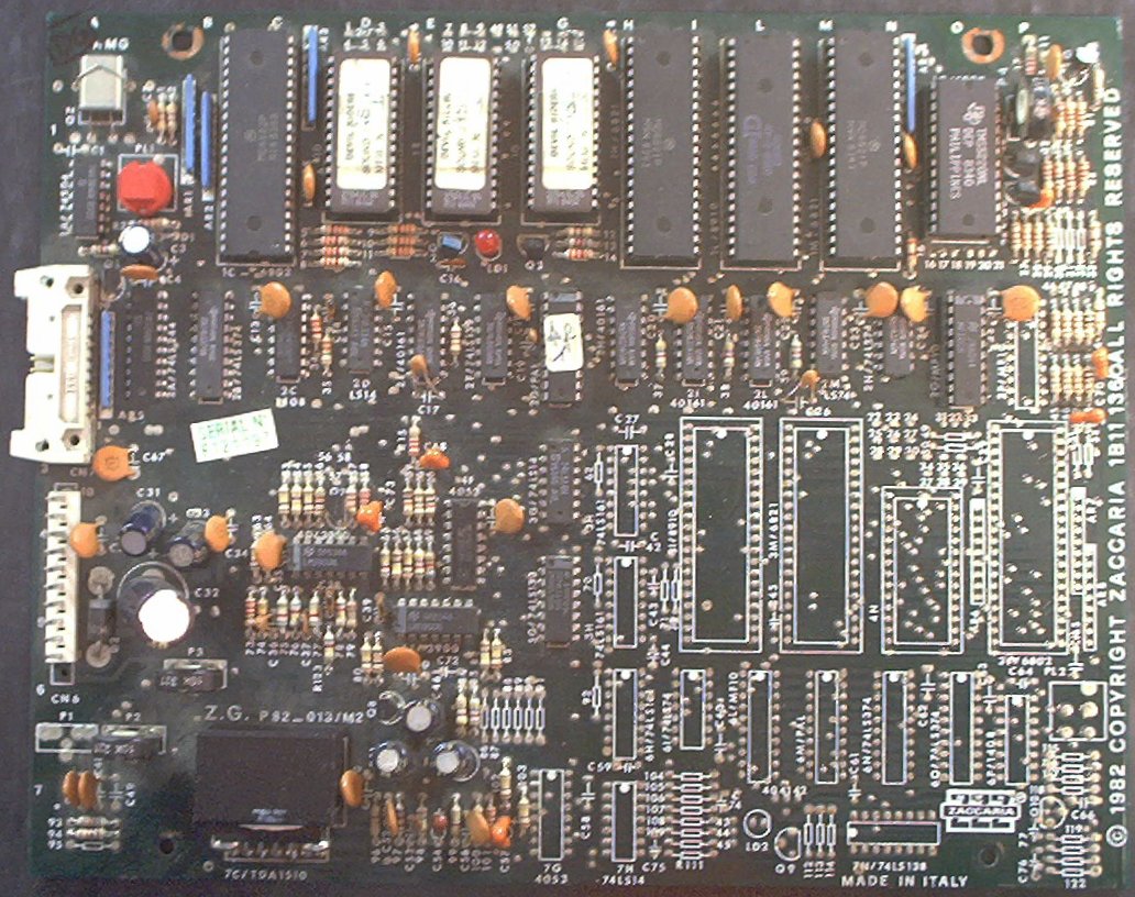
Used on Farfalla, Devil Riders, Time Machine, Magic Castle, and Robot, this board also features both sound and speech. A 6802 CPU on the board does the work, and will run independantly of the game's CPU board. Electronic sound effects are generated via a GI AY-3-8910 and/or a 1408 DAC, and sampled speech clips are recorded in ROMs on the board played via a TMS5220 speech chip. There are adjustment pots for each circuit to adjust their relative volume, and a final mix and amplification stage that feeds the sound to the single speaker mounted in the bottom of the cabinet. There is a volume pot mounted near the coin door to adjust the final volume. There is a self-test button on the sound board that will confirm that the board is working, though the game's built in diagnostics actually run through all of the sound and speech items in the ROMs.
Pressing the self test button on this board causes the board to perform several self checks which are confirmed by the LED flashing, then play a couple of sounds and at least one speech clip from the ROMs. This can be done with the Sound Board disconnected from the CPU to confirm that the board is working.
The LED flashes and their meanings:
| Flash | Test |
|---|---|
| 1 | CPU RAM tested OK |
| 2 | PIA 1 (IC15) - Sounds tested OK |
| 3 | PIA 2 (IC14) - Speech tested OK |
| 4 | Sound generator tested OK |
| 5 | Speech synthesizer tested OK |
There are two revisions of the this board, which is an updated/enhanced design from the earlier 1B1170. It has doubled the sound and voice capabilities, but that area of the board is unpopulated on all of the ones I have seen. The first version of this enhanced board is part number 1B11136. There is also part number 1B11136/0, a slight update from the 1B11136 board, where a potentiometer has been added to the speech section at location P4, allowing the speech speed/pitch to be adjusted.
It appears that the changeover from 1B11136 to 1B11136/0 may have happened during the production of Farfalla. The schematics package for my Farfalla includes only the 1B11136 board, though my game came with the 1B11136/0 board. I have seen Farfalla board sets with both revisions of the 1B11136 board.
Adjusting the speech speed and pitch with the 1B11136/0 board is easy, just turn the potentiometer. Adjusting the speed and pitch on the 1B11136 board should be possible, though somewhat more difficult. The schematics for the 1B11136 board do not show a couple of resistors where the 1B11136/0 board has the adjustment pot in the upper right hand corner, yet the 1B11136 board has one or two resistors located there, labled "P" and "S".
On the 1B11136, just to the right of the TMS5220 speech chip, is resistor R18 (100K). Next to it should be a resistor labeled "S" (10K), and an empty pad labled "P".
On the 1B11136/0, R18 is moved out of the way, and is changed to 82K, "P" and "S" are deleted, and a 47K pot (P4) is added. P4 is in series with R18, and provides an adjustment of the speech speed and pitch. When turned all the way up (47K) on mine, the female speech sounds almost the same as the male speech. When turned all the way down (0K), both voices sound like Mickey Mouse. Mine sounds best when P4 is adjusted to about 30K.
The 1B11136 board has R18 and "S" in series, for about 110K ohms of resistance. The 1B11136/0 has R18 and P4 in series, and 82K + 30K is about 112K ohms. Adjusting the speed and pitch on the 1B11136 can be accomplished by varying the resistors at R18 and "S" until it sounds good.
Another possibility would be to find a small 47K pot to fit the pads in place of "S",and replace R18 with an 82K resistor. Something like Mouser P/N 72-T7YA473MB40 (Vishay P/N T7YA473MB40) might work well for this, which would effectively upgrade a 1B11136 to a 1B11136/0.
I have seen a couple of 1B11136 sound boards with problems where the board still appears to work, but the sounds are wrong, missing, or are VERY faint when played. Some sounds may be ok, others very faint or distorted. This is caused by a failed or missing MF10 filter IC at location 2O on the board. This is because the 8910 sound generator has three output channels, all of which are used by the game. But, only two of the channels are fed through the MF10 filter. So, the sounds that are primarily channels "A" and "B" sound wrong, but sounds that are primarily channel "C" sound fine. Sounds produced via the 1408 DAC do not go through the MF10, so those will sound fine.
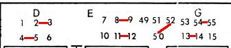
The schematics for Time Machine, Farfalla, Devil Riders, Robot and Magic Castle show jumper positions that are not labled on the board silkscreen. Worse, the jumpers as shown in the schematics book, on the jumpers page, are wrong.
There are three unlabled jumper pads on the boards, just above the numbers 13, 14, and 15. These are jumpers 53, 54, and 55. These are shown in the board schematics. The 13, 14, and 15 are the pads below these numbers.
As shown, Farfalla, Magic Castle, Devil Riders, and Robot are wrong. They show 53/54 connected, when it should be open and 54/55 should be connected instead.
 |
 |
| Jumpers, as shown (wrong) | Jumpers, with all points labled |
 |
 |
| Jumpers: Time Machine | Jumpers: Farfalla |
 |
 |
| Jumpers: Devil Riders | Jumpers: Magic Castle |
 |
|
| Jumpers: Robot |
The jumper labled 50 is actually the three pads below 49, 51, and 52. These three are connected by a trace on the back side of the board. The diagrams above show 50/52 connected on an angle, but it can also be connected verticly between the rightmost pad of 50 and 52.
The disc capacitors C69, C71, C70, and C73 should be 0.22uF, not 0.22nF as shown on the schematics for this board. The parts list in the manual is correct.

Picture by Frank Gigliotti
Picture by Frank Gigliotti
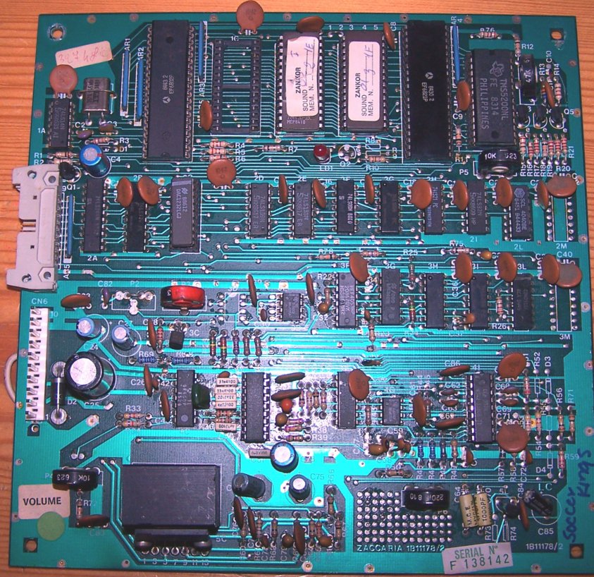
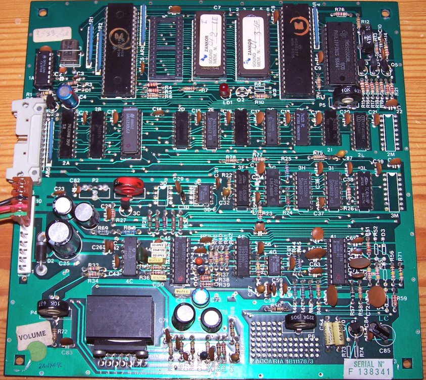
Used on Clown, Pool Champion, Blackbelt, Mexico '86, Zankor, and Spooky, this board seems to be a step backward from the 1B11136. It offers simpler sound effects and music, and has speech capabilities that were not even used on some games.
There are at least three revisions of the 1B11178 board. The 1B11178/1 is the earliest I have seen. It has a six-pin Molex header at CN6, leaving the upper four pads unpopulated, and it used the TMS5200 voice synthesizer. Clown, Pool Champion, and Blackbelt use this board.
With Mexico '86, the 1B11178/2 added the missing four pins to CN6 to supply power to the 1B11181 backround music daughterboard. It is otherwise unchanged from the 1B11178/1.
For Spooky and Zankor, the 1B11178/3 has the fully populated CN6, plus a 220K Ohm trimpot has been added (P6) and a second TL081 (3D) amplifier. Additionally, the voice synthesizer was changed to the TM5220.
Unlike the earlier games, the LED on this board has no self test meaning. It is simply a power indicator. If the +5v supply is working, the LED will be on. The schematic for Pool Champion indicates a couple of resistors (R8/R9) and a transistor (Q2) are used to turn on the LED, but on the boards I have seen, R8/R9 are not populated, and Q2 is replaced (factory) with a jumper wire.
Also unlike the earlier 1B11136 and 1B1170, there is no "self-test" button on these boards. That limits the simple troubleshooting possible without either swapping parts, or testing parts with a logic probe or o'scope to see what is working or not.
Fortunately, these boards share the same 7-bit communciations protocol that the other 2nd generation games used so that the CPU can tell the board what to do. See the Communications section below for details.
It appears that the 1B11178/1 and 1B11178/2 use the TMS5200 speech synthesizer, while the 1B11178/3 uses the TMS5220. These are similar, but incompatible. Be sure to use the correct part if replacing one of these. All three revisions use the same 6802 CPU and 6821 PIA, and the DAC1232 to produce sound effects.

Picture by Frank Gigliotti
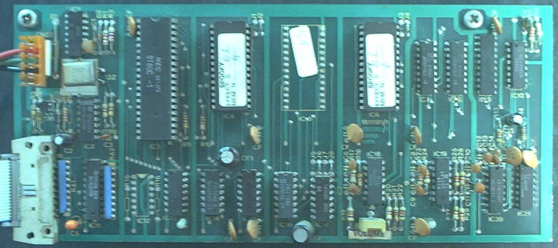
This is not a full sound board, but is a daughterboard as used on Zankor (1B11181/0) and Spooky (1B11181/1). It mounts on top of the 1B11178/3 sound board, and is connected to it via a (power) wiring harness and an extention of the ribbon cable. It provides background music capabilities.
There are two known revisions of the 1B11181 board. Between the 1B11181/0 found on Zankor and the 1B11181/1 found on Spooky, there were 2 chips (IC9, IC10) and 7 resistors (R22-R28) added, and one capacitor was removed. Many existing chips/resister/caps were renamed but still exist on the 1B11181/1 board.
| 1B11181/0 | 1B11181/1 |
|---|---|
| 3 sound chips | 2 sound chips (ic5 is soldered) |
| Jumper 9/10 available for inc vol. | Jumper 9/10 removed |
| IC9 added (74LS373) | |
| IC10 added (MC1408P) | |
| IC9 | renamed to IC11 |
| IC10 | renamed to IC12 |
| IC11 | renamed to IC13 |
| IC12 | renamed to IC14 |
| IC13 | renamed to IC15 |
| IC14 | renamed to IC16 |
| IC15 | renamed to IC17 |
| IC16 | renamed to IC18 - Replaced with TL084 |
| c16 onboard | c16 removed |
| c1 | renamed to C5 |
| AR1 | renamed to RA1 |
| AR2 | renamed to RA2 |
| R11 | renamed to R15 |
| R12 | renamed to R16 |
| R22-R28 missing | R22-R28 added |
Both the 1B11181/0 and 1B11181/1 obtain power via the wiring harness connection from the 1B11178/3 board.
| Pin | Voltage | Wire Colour |
|---|---|---|
| 1 | GROUND | BLACK |
| 2 | -5v | GREEN |
| 3 | +5v | RED |
A 1B11181/1 (Spooky) daughterboard can be used in place of a 1B11181/0 (Zankor) by removing R27 and R28, then changing the jumpers.
| J1 | J2 | J3 | J4 | J5 | J6 | J7 | J8 | |
|---|---|---|---|---|---|---|---|---|
| Spooky | Out | In | Out | In | Out | In | Out | In |
| Zankor | In | Out | In | Out | In | Out | In | Out |
Picture by Frank Gigliotti
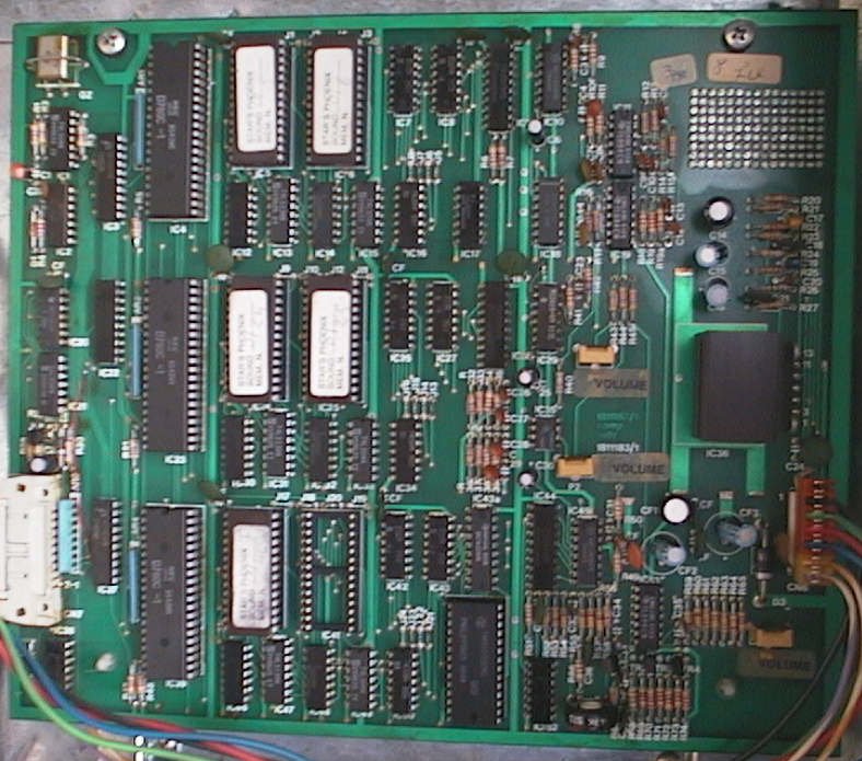
Used on Stars Phoenix and New Stars Phoenix this board seems to be a combination of the 1B11178 and 1B11181 boards, condensed back down to a single circuit board. It offers backround music, sound effects and speech capabilities.
This board has 3xZ80 CPUs on it. The top one is used to generate the background music, the middle one is used to generate sound effects, and the bottom one is used to generate the speech.
The TDA1510AQ amplifier IC used on these sound boards is not a common part in the US, though it appears to be more common in Europe. Be careful not to short the speaker terminals, or otherwise overload the amplifier outputs, as it will fail instantly. These are expensive, around $15-20 per chip. Until recently, the only source I had for them is an electronics supplier in London, England, but they have now been found at AmpsLAB. It also looks like NTE1802 may be the same part, but I have not yet tried one of these to prove it.
The Q or AQ on European IC normally indicates the legs on the chip are quilled ie alternate legs are staggered.
The CPU communicates with the sound board via a 7-bit protocol. There are eight data lines, but the eigth one is tied to the IRQ line of the CPU on the sound board. This line is always High, except for when it goes Low to trigger an IRQ. There is an ACK (acknowledge) return line from the Sound board to the CPU to let the CPU know that the requested sound has been played. Additionally, there is a line used to control the reset pin of the processor on the sound board, so that the the main processor on the CPU board can boot the processor on the sound board.
Bits 0...6 are used to tell the sound board what to do. High is a "1" and Low is a "0". The CPU normally holds all bits Low except for bit 7, but allows the required bits to go High before pulling bit 7 Low (IRQ). When bit 7 goes Low, then returns to High, the sound board CPU reads the value from the input bits by pulling the chip select line (pins 1 and 19) on the 74LS244 at IC2A Low, and plays the associated sound. Any time that bit 7 is High, the sound board can be interrupted from playing the current sound to play a new one.
Some sounds (on the 1B1170 and 1B11136) are the background sounds. These, once started, will continue to play in a loop until an IRQ with all data bits Low ("0") is seen. If interrupted by another sound, the other sound will play, then the board returns to the background sound. If another background sound is called, the first one stops and the new one starts.
I have mapped out the values for some of the games using the 1B11178, 1Blll36 and 1B1170 sound boards. I assume that the other games have a similar map, though I have not mapped all of them out yet. For 1B11136 and 1B11178, the sound number displayed during the sound test is 6 less than the decimal value of the bits used to tell the sound board what to play. For the 1B1170, the sound number displayed is 16 less than the decimal value of the bits used. I can't explain why they did that, maybe for capabilities they didn't use or used on later games. For example, sound 0 (as seen in the game's Sound test) on Farfalla is played by putting a 6 (000110) on the data pins and triggering IRQ. Sound 9 is 15 (0001111). This continues up to sound 25 (31). The next eight (32 through 39) are the commands to start the background sounds. 40 and 41 are not used, and the speech calls are 42 through 61. 62 and higher are not used. I do not yet know how the 1B11178 and 1B11181 work, as the 1B11181 is used for playing backround sound/music while the 1B11178 plays sound effects, but I assume that they are similar.
The 1B11136 sound board has three distinct and separate sections, not including the un-populated lower half of the 1B11136 (that would be four).
Some sounds are speech calls, via the 6821 and 5220. Some sounds are analog sound effects, generated by the 8910, fed through the MF10 (sort of). The third set are digital sounds, via the 1408 DAC chip. The digital ones are converted to analog, then are mixed with the analog outputs of the MF10s before being fed to the amp.
The 74LS161s at IC2H and IC2I, and 74LS74 at IC2M are used as an adjustable clock circuit that feeds in to the MF10s. A 'scope on them is interesting to watch, as they adjust the clock pulses to vary the sounds being produced, in addition to the varying frequencies being put out of the 8910 output pins ("A1", "B1" and "C1").
The MF10s are interesting, too. In reading the data sheet on them, the way they are wired in to this circuit doesn't make any sense at all. This chip seems to have quite a few capabilities, all of which are disabled. A 'scope on the output pins (1,2,3,18,19,20) shows the output waveforms nicely, though.
The AY-3-8910 has three output channels. All three are used, even though "C1" is fed in to the MF10 that isn't installed. That threw me at first until I figured out that there's a set of resistors connecting the input "C1" to the outputs, and a jumper that shorts the outputs, bypassing the MF10. They use all three output channels from the 8910, but some sounds are heavy on the "c" channel, while others are weighted more on the "a" or "b" channels. If the MF10 at IC2O is missing or bad, the sounds from the 8910 range from missing to distorted to sounding ok, depending on how they use the three channels. A bad MF10 has no effect on the sounds from the DAC circuit.
David Gersic [an error occurred while processing this directive]
Copyright © 2001. All rights reserved.
This document may be freely distributed so long as the content is not modified.