The power supply board takes the input voltage from the transformer in the main cabinet, and generates the +5, +12, +39, +170 and -5 voltages needed for the logic, lamps, solenoids, and display circuits.
The input Molex connector at the bottom right corner (CN1) of this board can overheat with time, scorching the housing and building up resistance in the connector pins. Check here for any signs of overheating and replace the connector and header as necessary.
The fuse clips used are cheap and tend to corrode and weaken over time. They are also a non-US-standard size. Replace all of the fuse clips with high-quality ones (like the ones Mouser sells as part number 534-3513). To do this, the board will have to be modified by drilling holes to mount the clips properly. The solder pads for the fuse clips are large enough to allow 2 x 1/16" holes to be drilled to allow a normal fuse clip to be soldered in place. Enlarge one hole on each side, and add one new hole to fit the new fuse clip in place.
There are three bridge rectifiers mounted under the large heat sink in the middle of the power supply board. If one of them fails, you should replace all three of them while you already have the board out and are working on it. Two of the three are lug-type bridges and require a soldering iron that can deliver enough heat to work a large joint. Don't try this with a 15W Radio Shack soldering pencil!
I have seen Power Supply boards with three lug-type bridge rectifiers, and boards with two lug-type bridges and one (P2) with pins. The board itself has holes for either a pin or lug bridge at P2. Use whatever is available.
The schematic / parts list calls for these bridge rectifiers:
| Bridge Rectifier | Part Number | Rating |
|---|---|---|
| P2 | KBPC 8005 | 50V 8A |
| P3 | KBPC 10005 | 100V 10A |
| P5 | KBPC 1002 | 200V 10A |
You can substitute a higher rating for any of these. These:
| Bridge Rectifier | Mouser Part Number | Rating |
|---|---|---|
| P2 | 583-BR1005 | 50V 10A |
| P3 | 583-MP254 | 400V 25A |
| P5 | 583-MP254 | 400V 25A |
Before trying to troubleshoot a game in an unknown state, verify that the transformer is configured for the correct line voltage and has the correct fuse installed for your line voltage, then verify that the power supply is getting the correct input voltages and producing the correct output voltages.
Disconnect CN1 from the power supply board and test the transformer first. The correct way to test a transformer with a meter is to read voltages between pairs of pins in the connector. Do not attempt to read a voltage compared to the chassis ground, you will get approximately half the voltage reading that you would expect to see. Put your DMM on the appropriate VAC range before testing each pair of pins in this connector.
| Pin 1 | Wire Colour | Pin 2 | Wire Colour | Voltage |
|---|---|---|---|---|
| 1 | Red | 2 | Red | 165VAC |
| 5 | Yellow | 6 | Yellow | 10.5VAC |
| 9/10 | Green/Green | 11/12 | White/White | 6.5VAC |
| 7 | Blue | 8 | Blue | 43VAC |
| 3 | Brown | 4 | Brown | 10VAC |
After verifying the input voltages from the transformer, turn the power to the game off and reconnect CN1 to the Power Supply board. Disconnect the Molex connectors from the Power Supply that go to the Driver and Sound boards. Disconnect the ribbon cables from the CPU board that go to the Driver, Sound, and Display boards. Disconnect the Molex connectors from the CPU that go to the switch matrix. This leaves just the Power Supply and the CPU connected.
Turn the power on to the game, and the CPU should boot up (see CPU Startup). There are several test points on the Power Supply board to check:
| Test Point | Voltage |
|---|---|
| TP1 | 170VDC |
| TP2 | 12VDC |
| TP3 | 5.6VDC |
| TP4 | 5VDC |
| TP5 | 39VDC |
| TP6 | -5VDC |
| TP7 | Power Failure (note) |
| TP8 | Ground |
Put the black lead of your DMM on TP8, and use the other lead to probe these test points. On some boards, there are nice little wire loops soldered to the test points. On others, there are none. I have found that it is easier to test these with the loops, and have taken to installing them. You can use any scraps of 18 ga. wire, strip the insulation, and solder in place. Keep the loops short, no more than 1/4" tall.
Note:
The Power Failure test point is a logic level output of a LM339 at IC1 that shows whether the Power Supply is putting out correct voltages for the CPU board to boot up. It is tied to the reset (pin 16) pin on the CPU. The POWER FAILURE line inhibits the reset circuit from acting until the power has stabilized. There are two voltages being monitored via IC1.The LM339 uses the +12v filtered DC supply as a reference voltage. This is supplied at (C) in the schematics (IC1 pins 5 and 11). The first voltage monitored is the +12v, via a 5.6v Zener diode, to compare to the reference +12.
The other monitored voltage, at (B) in the schematics, is used to control the transistors at TR4 and TR5. These, in parallel, control the POWER FAILURE line.
On the Power Supply schematics, (B) and (C) are the inputs to the LM339 on pins 4 and 10. Pins 5 and 11 are reference voltages. Outputs of the LM339 at pins 2 and 13 are controlled by comparing pin 4 / 5 and pin 10 / 11. The outputs switch the transistors TR4 and TR5.
On initial power up:
As the power supply stabilizes:
On the CPU board, POWER FAILURE comes in on CN9 pin 3. Initially LOW at power up, this keeps the RESET line to IC9 LOW via the LS14 at IC13. When the power supply stabilizes and POWER FAILURE is no longer pulled LOW by TR4 or TR5, the pullup resistor at R34 on the CPU board should then pull IC13 pin 11 HIGH. This allows the reset circuit to toggle the RESET pin on IC9 and the CPU should boot and start running.
A voltage drop on the Power Supply board being seen by the LM339 would result in turning on TR4 or TR5, Grounding the POWER FAILURE line so that a LOW signal is sent to the RESET pin on IC9, forcing the game to reboot.
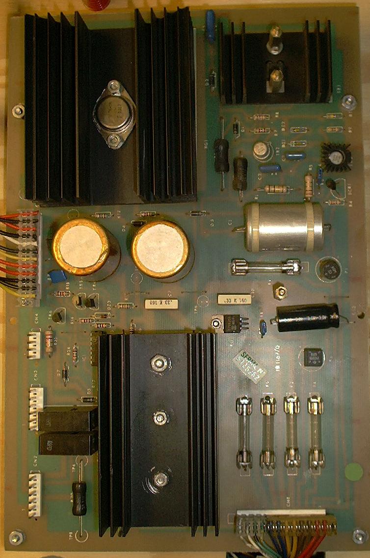
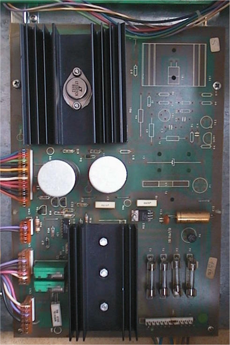
There are three Zaccaria power supply boards that I have seen. The earlier board, part number 1B1167, was used in Soccer Kings and Pinball Champ. During the Pinball Champ production run, a slight modification was introduced, as part number 1B1167/0. The 1B1167/0 power supply board was used in all of the games after Pinball Champ. The differences are minor, and the boards appear to be plug-compatible, but the older 1B1167 board may not work quite the same in a newer game.
Differences between 1B1167 and 1B1167/0:
The 1B1167 and 1B1167/0 boards are physically interchangable, and are plug compatible as well. A 1B1167/0 board should work in whatever game originally came with a 1B1167, but when a 1B1167 board is installed in to a newer game, the controlled lamps may behave a bit differently.
In my Farfalla, with a 1B1167, the controlled lamps would turn on normally, but would not turn off normally, leading to some strange looking light effects.
It appears that the additional TR6 is responsible for allowing them to turn off correctly. TR6 is used in conjunction with the LM339 at IC1 to cut the first .7V from the ascending voltage level, and the trailing .7V from the descending voltage level. This increases the time that the voltage supplied to the lamp SCRs is at a true 0v, allowing the SCR to turn off reliably.
On their last regular game, Zaccaria introduced LED-based score displays, and a modified 1B1167 power supply board that eliminated the parts for the 170V high voltage displays. There is a jumper added to the back side of the board between CN5 pin 12 and TP1 to provide +12VDC to power the LEDs on the displays. Other than the missing parts, the board appears to be identical to the 1B1167/0.
There is an error in the schematic for the 1B1167/0 Power Supply board. The voltage regulator, a 79M05 is shown connected backwards. The corrected circuit should look like this:
Note the change in the polarity shown for the bridge rectifier. Looking at the schematic for the 1B1167 board, it appears that when they added the components, they also re-arranged the schematic and made a mistake in the way the bridge rectifier at P4 is shown connected to the regulator.
Also, the arrangement of R11 and D3 is backwards. Voltage from bridge rectifier P2 goes to R11, then D3.