As the games and technology evolved through the late 1970s and in to the early 1980s, the 1st generation games quickly outgrew the simple " beep" and "boop" noises that the oscilator on the Driver board could produce. They added first a simple dedicated sound board, then replaced it every couple of games with a larger and more capable design. The result is that in ten games, there are four different sound boards, and the first three games used the Driver board. That works out to be a new sound board every other game. By today's standards, none of these is very complicated or full featured, but in their day they were pretty good.
Used on Shooting the Rapids, Hot Wheels, Fire Mountain, and some Star Gods. This was a basic oscillator board with sixteen different sounds selected by a four bit address bus.
Used only on Star God and a few Earth Wind Fire, and used a microprocessor and 2716 eprom, but stayed with the four bit address bus.

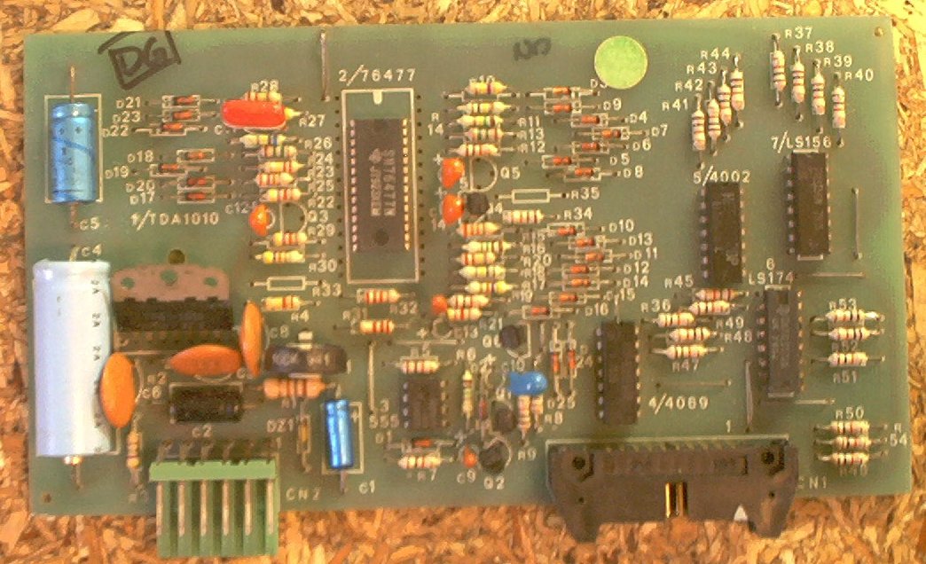
Used on Space Shuttle and Earth Wind Fire and was almost identical to the 1B1144 but with a different board layout. It uses an 8035 processor, a single 2716 ROM, and a 1408 DAC to produce sounds via a TDA1010 amplifier. The game sound volume is adjusted via the pot on the board.
Schematics Error: The 1B1146 schematics show the CPU as an 8085. It should show an 8035.
Schematics Error: The 1B1146 schematics only show IC10 as a 74LS373. In reality, the board can be configured for IC10 to be a 74LS373 or a 74LS374. There is an unlabled jumper next to IC3 that is not installed if the board is configured for IC10 to be a 74LS373. To change IC10 to a 74LS374, cut the trace that runs from one of the jumper pads to IC8 pin 11, the install the jumper. This inserts IC3 between IC8 pin 11 and IC10 pin 11. The signal leaves IC8 pin 11, goes via the installed jumper to IC3 pin 6. It comes out IC3 pin 5, and goes to IC8 pin 11.
Schematics Omission: There is no information I have been able to find in the schematics as to how the power supply for the 1B1146 and 1B1146/2 is wired.
The pins on CN2 are, from right to left:
| Pin | Wire Colour | Description | Connects To |
|---|---|---|---|
| 1 | Blue | 12VAC input | CN4 pin 2 |
| 2 | Yellow | 12VAC input | CN4 pin 1 |
| 3 | Green/Brown | 12VDC input | CN4 pin 4 |
| 4 | Green/Yellow | Ground | Cabinet Ground |
| 5 | Black | Speaker | Cabinet Speaker |
| 6 | Red | Speaker | Cabinet Speaker |
Looking at the Power Supply schematics, CN4 pins 1 and 2 are actually 7.5VAC.
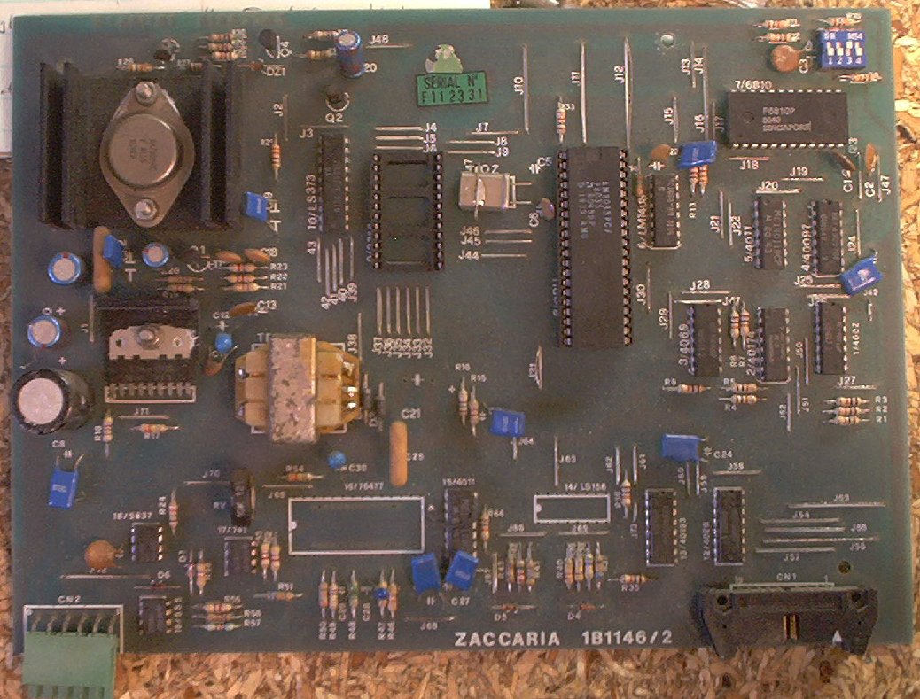
Used only on Locomotion and was basically a fancy version of the normal 1B1146. The 1B1146/2 adds the ability to play a backround "chuff chuff" train sound via an SN76477 sound synthesizer, but is otherwise the same as the 1B1146.
Both the 1B1146 and the 1B1146/2 have a four pin DIP switch in the upper right hand corner of the board. They are:
| SW3 | SW4 | Sounds |
|---|---|---|
| off | off | Set one - basic bings and boops This set reminded me most of early Williams System3 games like World Cup and Hot Tip. |
| on | off | Set two - electronic sounds This set reminds me of Williams games like Firepower and Defender. |
| off | on | Set three - more electronic sounds |
| on | on | No sounds at all |
Schematics Error: The 1B1146/2 schematics show two different parts as "IC12".
The TDA1010 amplifier IC used on these sound boards is rated for 10W output, and appears to have been used in automotive applications (where it's rated for only 6W output), so it may not be too hard to find spares or replacements. So far, I have not needed to replace one.
The CPU communicates with the sound board via the same ribbon cable that the displays are connected to.
For the 1B1146 and 1B1146/2 boards, the communications protocol is to load 0x06 on the Addr lines, load a data byte 0x01...0x?? on the Data lines, then strobe the S3 select line. The board latches the data via IC2, and plays the selected sound. To clear the latched data, load 0xFF on the Data lines, 0x06 on the Addr, and strobe S3. This has to be done before another sound can be played.
Putting a 'scope probe on R24 (1B1146) or R52 (1B1146/2) allows the sound waveform to be seen prior to reaching the amplifier. This can help if the rest of the board is working but the amplifier is blown. Set the 'scope for 1V 1mS resolution.
The pins on CN2 are, from right to left:
| Pin | Description |
|---|---|
| 1 | 12VAC input |
| 2 | 12VAC input |
| 3 | 12VDC input |
| 4 | Ground |
| 5 | Speaker |
| 6 | Speaker |
Connect a 12VAC supply to pins 1 and 2. Connect 12VDC and Ground to pins 3 and 4. Connect, in series, a speaker and a 47 Ohm resistor, to pins 5 and 6.