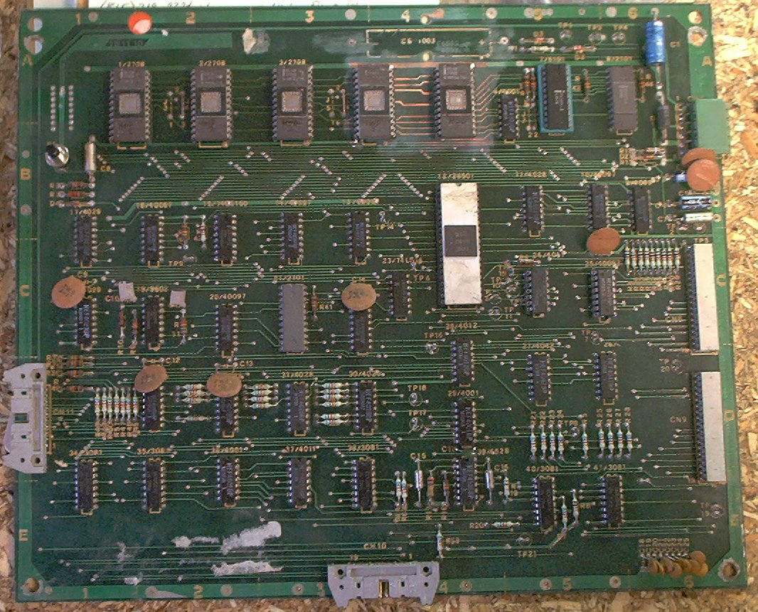
This board houses the CPU chip, game ROMs, game RAM, CMOS RAM with battery, and the circuitry for the switch matrix. It has connectors for power, switch matrix send/return lines, and ribbon cables to the driver board and displays. Unlike most other solid state pinball manufacturers, Zaccaria used a Signetics 2650A CPU chip for their boards, which you can see as the large (40 pin) chip in the centre of the board.
Click on the thumbnail above for a larger picture of a Zaccaria CPU board. This one has already had the (leaking) battery removed and the damaged area cleaned and neutralized.
The major areas of this board are:
| Pin | Voltage |
|---|---|
| 1 | 170VDC |
| 2 | Ground |
| 3 | Not Used |
| 4 | 12VDC (VDD) |
| 5 | 5VDC (VCC) |
| 6 | -5VDC (VGG) |
The biggest worry with a Zaccaria CPU board is the NiCd battery pack used to maintain the CMOS memory when the game is powered off. This battery pack is mounted at the top of the circuit board, in the center. If it starts to leak, the battery fluid runs down the board and ruins every component in its path. If you have a non-working Zaccaria game, this is the first thing to look for. If yours is working and hasn't leaked, PLEASE get the battery off the board and either use a 1F memory backup capacitor, or mount a remote battery immediately. If the battery has leaked, Clay's web site has a good recovery procedure for dealing with the corrosion and damage. After cleaning up and neutralizing the leaked fluid, remove and replace all components that were touched by the battery fluid, and all sockets on the board. Inspect the connectors and ribbon cables for signs of corrosion and replace as necessary.
To replace the original battery, a 1F 5.5V computer memory backup capacitor like Jameco P/N 142957 or Mouser P/N 555-1.0Z5.5 can be mounted on the CPU board in place of the battery pack and short leads used to connect it to the battery (+) and (-) traces, or a fly lead can be connected where the battery used to be and used to reach a remote battery pack.
To mount a remote battery pack, cut two wires to about 16" long, and solder them to the battery (+) and (-) pads. The other end I solder to a .100" two-pin connector snipped from an old PC floppy drive controller. I add a drop of JB Weld two part epoxy, then heat-shrink the connector, forming a small plug that is just the right size to connect a Radio Shack rechargable portable phone battery (Part #23-197, 3.6V, 350mAh, NiCad). Mount the battery on the left wall of the backbox with a velcro strap stapled to the wood, and you should never have to worry about battery leakage again. Replace the battery every few years, just to be on the safe side.
There are many logic test points on the CPU board:
| Test Point | Signal | Purpose |
|---|---|---|
| TP1 | VBB | +5V Battery |
| TP2 | VDD | CN7: +12 |
| TP3 | VCC | CN7: +5 |
| TP4 | GND | CN7: Ground |
| TP5 | VGG | CN7: -5V |
| TP6 | Signal | CPU: RESET |
| TP7 | Signal | CPU: FLAG |
| TP8 | Signal | CPU: SENSE |
| TP9 | Signal | CPU: CLOCK |
| TP10 | Signal | CPU: OPREQ |
| TP11 | Signal | CPU: M/IO |
| TP12 | Signal | CPU: WRP |
| TP13 | Signal | CPU: W/R |
| TP14 | Signal | CPU: RUN/WAIT |
| TP15 | Signal | CPU: INTACK |
| TP16 | Signal | CPU: INTREQ |
| TP17 | Signal | Interrupt Generator Output |
| TP18 | Signal | RUN |
| TP19 | Signal | Switch Matrix Row 1 |
| TP20 | Signal | Switch Matrix Column 0 |
| TP21 | Signal | CN10/CN11: RUN |
These are useful if the game is not running, or to confirm that it is running with the displays disconnected.
Four revisions of Zaccaria CPU boards for the games are covered by this document; part numbers 1B1110, 1B1110/0, 1B1110/1 and 1B1111/1a.
The 1B1110 is the original design for this board. It supports only five 2708 EPROMs for ROMs, and will work only in Winter Sports, House Of Diamonds, Shooting the Rapids, and Future World.
The 1B1110/0 is the first update to the board. Used on Hot Wheels, Fire Mountain, and Star God, there were two major changes, the first of which was adding support for 2K ROMs (2716 or CN13503N) at positions 1 and 3, although it appears that the changes to allow a 2K ROM at ROM #3 were incomplete, so that only a 2708 will work in this position. As part of the changes to support the larger ROMs, to make the board backward compatible with the 1B1110, jumpers J17 and J18 were added. J17 and J18 control where in the address space ROM2 appears by changing its Chip Select from IC11 output line 1 to IC11 output line 7. The other change is a "clear CMOS RAM" feature where the game will ignore and clear the contents of the 5101 if it is powered up with TP19 (Switch Matrix Row 1) connected to TP20 (Switch Matrix Column 0). This was likely to deal with problems caused by flakey 5101 CMOS RAM chips and failing batteries that could cause the contents of the 5101 to be corrupted; the earlier games could simply crash or even fail to boot.
The 1B1110/1 is the second update to the board. Used on Space Shuttle and Earth Wind Fire, this board introduced Switch Matrix Row 7. The 1B1110 and 1B1110/0 do not have CN9 pin 9 connected to anything. The 1B1110/1 has CN9 pin 9 connected to IC26 pin 15. This, and the previously unused Switch Matrix Row 6, are used to support the 1B1149 "Flipper Programming Board" (see below).
Finally, the 1B1110/1a was the last update to this board. It does not appear to have been manufactured, but designates a factory modification to the 1B1110/1 design. This board was used only for Locomotion, their last 1st generation game. To fully support having a 2K ROM at position 3, they cut the trace at IC11 pin 6 (which used to connect to IC39 pin 12) and connected it with a jumper wire to pin 1 of jumper position J2. IC39 pin 12 was then connected with another jumper wire to IC12 pin 18 (CPU, Address Bus 14). The effect of this is to place the upper half of the 2K ROM at position 3 above the data from the ROM at position 5 in the address space. Without these modifications, the upper half of ROM3 is not addressable.
Note that the 1B1110/1 is probably the most useful and versatile of these four revisions, since it has the RAM reset feature, and support for Switch Matrix Row 7. It would work for any game except for Locomotion, but could be modified in to a 1B1110/1a if needed. The 1B1110/0 is almost as versatile, since it has the RAM reset feature, and support for Row 7 is only important for the 1B1149 settings board, which could be ignored in a home environment. If needed, the 1B1110/0 could be modified by adding a jumper from IC26 pin 7 to CN9 pin 9, effectively turning it in to a 1B1110/1. The 1B1110/1a will only work in a Locomotion, but could be easily modified back to a 1B1110/1 with a few simple changes.
ROM Jumpers
| ROM1 Jumpers | ||
|---|---|---|
| Jumper | Signal | Connects To |
| J3 | AB10 | Pin 19 |
| J4 | VDD (+12V) | Pin 19 |
| J7 | GND | Pin 21 |
| J8 | VCC (+5V) | Pin 21 |
| J9 | VGG (-5V) | Pin 21 |
| J10 | GND | Pin 18 |
| J11 | VCC (+5V) | Pin 18 |
| J1 | Chip Select Control | |
| ROM2 Jumpers | ||
| J17 | Chip Select Control | |
| J18 | Chip Select Control | |
| ROM3 Jumpers | ||
| Jumper | Signal | Connects To |
| J5 | AB10 | Pin 19 |
| J6 | VDD (+12V) | Pin 19 |
| J12 | GND | Pin 21 |
| J13 | VCC (+5V) | Pin 21 |
| J14 | VGG (-5V) | Pin 21 |
| J15 | GND | Pin 18 |
| J16 | VCC (+5V) | Pin 18 |
| J2 | Chip Select Control | |
These jumpers control voltage, ground, and addressing pins on the ROMs. As far as I can tell, J7 and J11 should always be out, and J10 (2/3) should always be in. Similarly, J12 and J16 should always be out, and J15 (2/3) should always be in. I do not know what types of chips J7/J11/J10, J12/J16/J15 are intended to support.
| ROM 1 | |||
|---|---|---|---|
| Type | Size | Jumpers | |
| 2716 or TMS2516 | 2K EPROM | J8 (1/2) in | J9 out |
| J3 (1/2) in | J4 out | ||
| J1 in | |||
| J17 (1/2) out | J18 in | ||
| CN1350N | 2K ROM | J8 out | J9 (2/3) in |
| J3 (1/2) in | J4 out | ||
| J1 in | |||
| J17 (1/2) out | J18 in | ||
| 2708 | 1K EPROM | J8 out | J9 (2/3) in |
| J3 out | J4 (2/3) in | ||
| J1 out | |||
| J17 (1/2) in | J18 out | ||
| ROM 3 | |||
|---|---|---|---|
| Type | Size | Jumpers | |
| 2716 or TMS2516 | 2K EPROM | J13 (1/2) in | J14 out |
| J5 (1/2) in | J6 out | ||
| J2 in | |||
| CN1350N | 2K ROM | J13 out | J14 (2/3) in |
| J5 (1/2) in | J6 out | ||
| J2 in | |||
| 2708 | 1K EPROM | J13 out | J14 (2/3) in |
| J5 out | J6 (2/3) in | ||
| J2 out | |||
Notes:
ROM Types: The Texas Instruments TMS2516 is equivilent to everybody else's 2716 designs. It requires only VCC (+5V) to operate. The Texas Instruments TMS2716 is not compatible with anybody else's 2716 because it is a three-rail power supply device, similar to the 2708, requiring +5V, -5V, and +12V to operate, but uses pin 20 for the +12V supply. None of the jumpers on these boards configure them to put +12V on pin 20. This is probably not a big deal, as the TMS2716 is an oddball that nobody is likely to have, need, or want support for.
The CN13503N seems to be similar to the 2716 design, but with the additional -5V supply requirement typical of the 2708. Not much is available on this chip, but from the jumpers settings needed to support it (thanks, Frank, for figuring this part out), it appears to be a cross between the 2708 and the 2716, using +5V and -5V supply voltages, but with pin 20 as the Chip Select line.
There are some notes on Leon's site ( http://www.flipper-pinball-fan.be) on converting these boards to use 2716 EPROMs to replace the difficult-to-program 2708s. I don't use these adaptations, because I have an EPROM burner that supports the 2708 chips and a healthy supply of spares. As of this writing, Chris at http://www.pinballroms.com can supply 2708 EPROMs burned with the Zaccaria game image of your choice.
There is an error in the schematics for the 1B1110 CPU boards used in the earliest games (Winter Sports, Future World). The +12V (VDD) and -5V (VGG) voltages are shown on the wrong pins of the five ROMs. +12V (VDD) should be connected to pin 19, and -5V (VGG) should be connected to pin 21. By the time of the 1B1110/0 board revision (Hot Wheels), this error was corrected.
These two items would not ordinarily be found together, but it turns out that the GI lamp circuit is critical to the operation of these games. Without it, the game cannot boot. The reason is that the bridge rectifier P3 on the power supply board takes its AC input from the GI lamp circuit, and is labled as being a +5.3VDC (VRM) power supply output. Tracing this through the schematics, the only place it is used is to feed the RESET circuit on the CPU board. So, without a working GI lamp circuit, the CPU cannot start and the game will not boot. This makes the scorched connector problem on the 1B1109 board even more problematic, since it would affect the GI circuit input on the board, leading to a non-working game when the connector fails.
I have not seen many Signetics 2650 failures, even on badly corroded boards (the socket tends to protect the chip by being destroyed first), but have run in to CPU boards that were missing this chip. Replacements for this chip are scarce, but available. Note that Signetics made two processors, the 2650 and the 2650A. The 2650 runs at a slower clock speed than the 2650A. Zaccaria games require the faster 2650A processor chip. These were also used in some early home gaming consoles like the Emerson Arcadia 2001.
David Gersic
Copyright © 2001. All rights reserved.
This document may be freely distributed so long as the content is not modified.